Last updated: 01/19/99 20:17
These are some tips that follow the way I do things - use them or don't if you wish. I'm not going to go into detail that I've gone through in other pages at this web site. I'm simply going to help fill in some blanks.
![]()
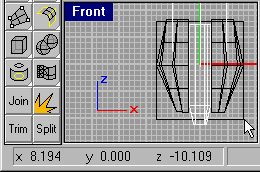 Units in
Total Annihilation are generally given a size (or "footprint") in terms of
roughly how much X- and Z-Axis space the unit takes on the screen. Each
"footprint unit" in Total Annihilation represents a 16x16 square when editing in
Rhino. A very small unit, such as the Arm Invader crawling bomb, is roughly 1x1,
while a larger unit, such as the Arm Merl, is roughly 3x3 (which means that in Rhino, the
unit will occupy the X- and Z-Axes from approzimately -24.0 to +24.0 when centered on the
origin). Note however, that a unit need not be exactly contained within the
boundaries of such a box, nor does it necessarily need to be square. The unit can
extend beyond the footprint boundaries, but should, for the sake of consistency, come as
close as possible. You can see in the figure to the left (which is a prototype for a
hovercraft kamikaze bomb unit), the nose of the unit extends slightly beyond the -8.0
boundary that would normally be used for a 1x1 unit.
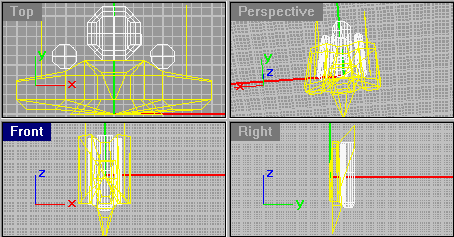 As
already mentioned, Total Annihilation units occupy a slightly different axis orientation
in which the X-Axis is left-right, the Z-Axis is front-back, and the Y-Axis is
up-down. When creating and viewing a unit model using Rhino, the "Front
View" is actually a bottom-up view (that is, you are actually underneath the
unit looking upwards!) of your model with the model's "front" facing towards the
bottom of your screen. (Thus, the "nose" of your unit will lie along the
negative Z-Axis). The "Top" view in Rhino is actually a view through your
unit from the "nose" of the unit looking backwards (which is important so you
don't confuse your left from your right). Note: I got confused myself writing
this paragraph, so please correct me if I have it backwards somewhere.
The simplest shape to work with in Rhino is a cube, for obvious reasons. ![]()
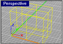 You can use the
built-in cube-making tool in Rhino, but it is recommended that you use (import) the sample
cube DXF file that comes with 3DOBuilder. Or, you can download the cube.3dm model, which is a simple cube you can input into
Rhino and play with as you wish. Rhino will not try to chop the sides of this cube
into pieces. The reason for wanting to use the DXF version is that Rhino doesn't
always do exactly what you expect when you convert your shape to a DXF model, and
sometimes splits the faces (which are already 4-sided polygons) into several 4-sided
polygons instead of one. By using a pre-existing DXF cube, you run a better chance
of ensuring that it'll only have one polygon on each face.
Keeping in mind that a cube only has 8 points to work with (at each of it's corners), you will need to use a series of cubes if you would like to create a markedly non-cubic shape for a unit (such as the elongated hexagonal shape of many of the hovercraft vehicles). You can copy your imported (or created) cubes by simply selecting the cube, pressing Ctrl-C to Copy, then Ctrl-V to Paste a new copy of the cube. Then, right-click and drag the replica cube to its new position. (Note that you can hold down the shift-key while dragging to ensure straight-line (aka "orthogonal") movements).
Move, scale, and rotate your cubes as you wish to sketch out the rough shape of your unit.
Once you've created the cubes you'd like to use in your model, the next step is to
"explode" ![]() the cube into the 6 individual surfaces that make up the cube. Select
all the cubes you want to explode, and explode them. Once you have exploded into
the individual surfacs, you will be able to better pull and stretch the cubes into shapes
that you desire more easily.
the cube into the 6 individual surfaces that make up the cube. Select
all the cubes you want to explode, and explode them. Once you have exploded into
the individual surfacs, you will be able to better pull and stretch the cubes into shapes
that you desire more easily.
For me, ![]() altering
the shapes of the cubes I've created involves grabbing and stretching the cube's control
points to their new locations.
altering
the shapes of the cubes I've created involves grabbing and stretching the cube's control
points to their new locations. 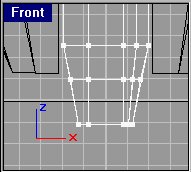 After exploding your cubes, you will choose
the option to Display Control Points within Rhino after selecting the object you wish to
work with. After doing so, points will be shown at the corners of each of the
selected surfaces.
Select the points you wish to move carefully. Remember that a point you see in one view may actually be several points that appear in the same position. When selecting points, hold down the Shift-key to add additional points to your currently selected set. In addition, clicking and dragging a box around the desired points works very well.
Be sure not to warp your shapes too much - remember that you will be dealing with flat 4-sided faces in the long run, so you don't want to introduce and "twisting" of your shapes. Holding the Shift-key down while moving your points will help to ensure you are moving them in a straight line.
When creating the Arm Fireball (my FlameThrower aircraft unit), I created the external tanks by extruding a simple hexagon shape into a long hexagonal cylinder. Although you may not need to do such a thing for your own unit, I put the steps here as FYI.
![]() Using
Rhino's Polygon tool, create a 2D shape that you wish to extrude (such as a hexagon or
octagon). This shape you create using this tool is called a "Planar Curve"
in Rhino.
Using
Rhino's Polygon tool, create a 2D shape that you wish to extrude (such as a hexagon or
octagon). This shape you create using this tool is called a "Planar Curve"
in Rhino.
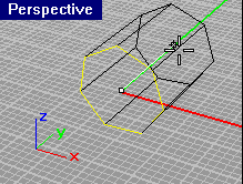 Once you
have your shape created, select it and choose Solid->Extrude Planar Curve
from the Menu Bar, and pull your shape in the direction you wish to extrude. (If you
chose an existing surfaces (that you created by exploding a shape) as your shape to
extrude, you will choose the Solid->Extrude Surface menu item).
Click your mouse one additional time to create your extruded shape.
After creating your new shape, you are actually left with 2 objects on your screen: the original 2D Planar Curve (or Surface), and the newly created shape. If you no longer need your 2D shape, you can now delete it.
After creating your shape, it is a shape like any other, such as the cubes that you may have already created in previous steps. Therefore, you will need to explode the shape if you wish to alter the shape by moving its control points.
It's actually easiest to create your unit in its entirety within a single Rhino model (save it while your working on it in Rhino's 3DM format). By doing so, you can be sure that all of your pieces line up right and are the proper size. When you are finished, however, you need to save each piece of your model separately so that each piece can be imported into 3DOBuilder and be assigned the appropriate parent/child relationships.
When I save pieces from Rhino in DXF format, I take the easy approach: Delete everything except what I want to save, then save the part (in DXF format, of course), then re-load my entire unit image. I repeat this process until all pieces have been saved away.
The most important thing here is to ensure that your pieces are aligned properly along any of the Axes that the piece may move along. When saved, each piece has it's own orientation in the 3D coordinates, and therefore must be aligned properly before each piece is saved. To explain this, here is an example (read and understand carefully): Look at the Core Raptor aircraft (or my own Arm Fireball - which used the Raptor as it's base design). It has two wings that "fold" down from an upright position to its normal flying position, then the wings return when the unit lands. All pieces rotate around one of the three coordinate Axes at the origin point (0,0,0). Thus, the point at which the wing pivots must be at the origin. If you followed by suggestion of building your entire model in a single file, your wings are most certainly not at the origin, are they? In this example, after removing all pieces of your aircraft except the wing you are saving, you will want to move the wing to line up with whichever Axis it will be rotating around before saving it. This will ensure that when you rotate the piece around that given Axis, it will rotate as you would expect.
Alignment issues such as this only arise if you are going to be turning or spinning a particular piece. Linear piece movements can be done regardless of how a piece is positioned.
(polygon mesh)